A bench supply set to 14.8 V delivers 14.8 V at 1 A and at 10 A. The battery pack it stands in for does not. Its voltage drops as the current rises, and the firmware that watches for low voltage only ever sees that drop on the real pack.
Yellow: a supply with no internal resistance. Blue: the same supply with the resistance you set. Red dashes: your device’s undervoltage cutoff. The dots sit at the load current you choose.
Why a stiff rail hides problems
Every battery has internal resistance. Pull current from it and part of the voltage is lost inside the battery, so the terminal voltage is the open-circuit voltage minus current times resistance. A 4S lithium-ion pack with 0.15 Ω loses 1.5 V at 10 A before your circuit gets any of it.
That drop is what a lot of firmware is written to handle. Undervoltage lockout, low-battery warnings, motor current limits that back off as the pack sags, DC-DC converters that have to stay stable with a soft input: none of it is exercised on a supply that holds 14.8 V no matter what. The first time it runs for real is on a customer’s battery.
Why a resistor in series is a poor fix
The usual workaround is a power resistor between the supply and the device. It does sag the voltage, but it has a fixed value, it gets hot (I² × R, shown in the last readout), and its resistance drifts as it heats. Changing the value means changing the part.
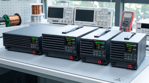
A UDP5000 does the same job in its control loop. You enter a resistance and the supply lowers its own output by I × R as the load current changes. Nothing on the bench gets hot, and the value changes from the front panel or over SCPI.
What the UDP5000 can set
The internal resistance works in constant-voltage mode and sets in 0.001 Ω steps on every model. The maximum depends on the model: rated voltage divided by rated current on the 40 V and 80 V models, and three quarters of that on the 160 V, 250 V and 800 V models.
| 400 W model | Rated output | Maximum internal resistance |
|---|---|---|
| UDP5040-40 | 40 V / 40 A | 1.000 Ω |
| UDP5080-20 | 80 V / 20 A | 4.000 Ω |
| UDP5160-8 | 160 V / 8 A | 15 Ω |
| UDP5250-6 | 250 V / 6 A | 31.25 Ω |
| UDP5800-2 | 800 V / 2 A | 300 Ω |
From the UDP5000 data sheet. The other 15 models are in the picker above.
Try this
- Pick the 4S pack and set the load to 10 A. The device sees 13.30 V, comfortably above a 12.0 V cutoff. Push the load past 18.7 A and the cutoff fires, even though the stiff supply still shows 14.8 V.
- Set the internal resistance to zero. The blue line lies on the yellow one, and the cutoff never fires at any current the supply can deliver.
- Pick the 13S pack on the UDP5040-40. Its 48.1 V is above what a 40 V model can output, so switch the supply to the UDP5080-20.
This is a resistance, not a full battery model. The supply holds the open-circuit voltage you set, so it does not discharge the way a battery does over minutes, and it does not copy the slower voltage recovery a cell shows after a load step. For testing cutoffs, warnings and converter stability at a known source resistance, it is the part that matters.
Battery values in the presets are typical figures for illustration. Measure your own pack, or take its internal resistance from the cell maker’s data sheet.
Programmable internal resistance on all 20 models. 40 V to 800 V, 400 W to 2000 W.
See the UDP5000 seriesRelated: UNI-T’s white paper on adjustable internal resistance · Constant voltage vs. constant current. UNI-T. Design. Debug. Deploy.™